
Powerful, regulated power supply. Simple adjustable stabilized power supply. Saturation and draft

Need for laboratory power supply with the ability to adjust the output voltage and the protection threshold for load current consumption arose a long time ago. Having worked through a bunch of material on the Internet and gained some insight from my own experience, I settled on the following design. The voltage regulation range is 0-30 Volts, the current supplied to the load is determined mainly by the transformer used, in my version I can easily draw more than 5 Amperes. There is an adjustment of the protection threshold for the current consumed by the load, as well as against a short circuit in the load. The indication is performed on the LSD16x2 LCD display. I consider the only drawback of this design to be the impossibility of transforming this power source into a bipolar one and the incorrect indication of the current consumed by the load in the case of combining the poles together. My goals were to power mainly unipolar power supply circuits, so even two channels, as they say, head on. So, the diagram of the display unit on the MK with its functions described above:
Current and voltage measurements I - up to 10 A, U - up to 30 V, the circuit has two channels, the photo shows voltage readings up to 78L05 and after, it is possible to calibrate for existing shunts. There are several firmware for ATMega8 on the forum, but not all have been tested by me. The circuit uses the MCP602 microcircuit as an operational amplifier, its possible replacement is LM2904 or LM358, then the op-amp power needs to be connected to 12 volts. On the board I replaced the diode at the input of the stabilizer and the power choke with a jumper; the stabilizer must be placed on a radiator - it heats up significantly.

To correctly display current values, it is necessary to pay attention to the cross-section and length of the conductors connected from the shunt to the measuring part. The advice is this: minimum length, maximum cross-section. For the laboratory power supply itself, a circuit was assembled:

It started up immediately, the output voltage adjustment is smooth, as well as the current protection threshold. The print had to be adjusted to LUT, this is what happened:
Connecting variable resistors:

Location of elements on the power supply board
Pinout of some semiconductors

List of laboratory IP elements:
R1 = 2.2 KOhm 1W
R2 = 82 Ohm 1/4W
R3 = 220 Ohm 1/4W
R4 = 4.7 KOhm 1/4W
R5, R6, R13, R20, R21 = 10 KOhm 1/4W
R7 = 0.47 Ohm 5W
R8, R11 = 27 KOhm 1/4W
R9, R19 = 2.2 KOhm 1/4W
R10 = 270 KOhm 1/4W
R12, R18 = 56KOhm 1/4W
R14 = 1.5 KOhm 1/4W
R15, R16 = 1 KOhm 1/4W
R17 = 33 Ohm 1/4W
R22 = 3.9 KOhm 1/4W
RV1 = 100K trimmer
P1, P2 = 10KOhm
C1 = 3300 uF/50V
C2, C3 = 47uF/50V
C4 = 100nF polyester
C5 = 200nF polyester
C6 = 100pF ceramic
C7 = 10uF/50V
C8 = 330pF ceramic
C9 = 100pF ceramic
D1, D2, D3, D4 = 1N5402,3,4 diode 2A - RAX GI837U
D5, D6 = 1N4148
D7, D8 = 5.6V Zener
D9, D10 = 1N4148
D11 = 1N4001 diode 1A
Q1 = BC548, NPN transistor or BC547
Q2 = 2N2219 NPN transistor
Q3 = BC557, PNP transistor or BC327
Q4 = 2N3055 NPN power transistor
U1, U2, U3 = TL081
D12 = LED
The finished boards look like this in my version:

I checked it with the display, it works fine - both a voltmeter and an ammeter, the problem here is different, namely: sometimes there is a need for a bipolar supply voltage, I have separate secondary windings of the transformer, you can see from the photo there are two bridges, that is, two completely independent ones from another channel. But the measurement channel is common and has a common minus, therefore it will not be possible to create a middle point in the power supply, due to the common minus through the measuring part. So I’m thinking of either making each channel its own independent measuring part, or maybe it’s not very often that I need a source with bipolar power supply and a common zero... Next, I present the printed circuit board, the one that has been etched so far:

After assembly, first thing: set the fuses exactly like this:

Having assembled one channel, I verified its functionality:


While the left channel of the measuring part is turned on today, the right one is hanging in the air, therefore the current shows almost maximum. I haven’t installed the cooler for the right channel yet, but the essence is clear from the left one.

Instead of diodes for now in the left channel (it is below the right board) of the diode bridge that during the experiments I threw out, although 10A, I installed a 35A bridge on the radiator under the cooler.

The wires of the second channel of the transformer secondary are still hanging in the air.

Bottom line: the stabilization voltage jumps within 0.01 volts throughout the entire voltage range, the maximum current that I could draw was 9.8 A, which was enough, especially since I expected to get no more than three amperes. The measurement error is within 1%.
Flaw: I can’t transform this power supply into a bipolar one due to the general disadvantage of the measuring part, and after thinking I decided that I couldn’t configure the terminals, so I abandoned the scheme of completely independent channels. Another disadvantage, in my opinion, of this measuring circuit is that if we connect the poles together at the output, we lose information about the current consumption by the load due to the common body of the measuring part. This happens as a result of paralleling the shunts of both channels. But in general, the power supply turned out to be not bad at all and will be available soon. Author of the design: GOVERNOR
Discuss the article DIAGRAM OF LABORATORY POWER SOURCE
A laboratory power supply unit (PSU) for a radio amateur is an essential device! You have to work with different devices or their elements. Accordingly, there is a wide range of energy consumers and all have different supply voltages. There is nothing left to do but purchase a ready-made power supply unit. But while shopping around in radio stores, I realized that it was not that cheap and decided that a simple, inexpensive power source would be enough for me to start with. Since I am, one might say, a beginner in this matter, I first turned to the literature, studied its operating principle and want to tell you what is needed for this.
The diagram of a simple laboratory power supply conditionally consists of two parts:
1) the power supply itself (transformer, diode bridge and capacitor) This is the main part; the power of the entire power supply depends on the choice of transformer parameters.
2) a small voltage regulator circuit (can be a transistor or a zener diode).

Required items:
- Transformer;
- Diode bridge;
- Zener diode __LM-317;
- Capacitors__C1 2200mkF, C2 0.1mkF, C3 1mkF;
- Resistors _____R1 4.7 kOm (variable), R2 200 Ohm;
- Voltmeter;
- Light-emitting diode;
- Fuse;
- Terminals;
- Radiator.

I already had a transformer (TS-10-1), I didn’t have to choose and spend money on it.
Now that all the elements are assembled, let's get started.
STAGE 1: Prepare the board.
(downloads: 1823)

STAGE 2: Solder the elements according to the diagram. If you do not have the opportunity to “etch” the board, you can make it “canopy”.
STAGE 3: We connect the board to the transformer, and our power supply is ready.
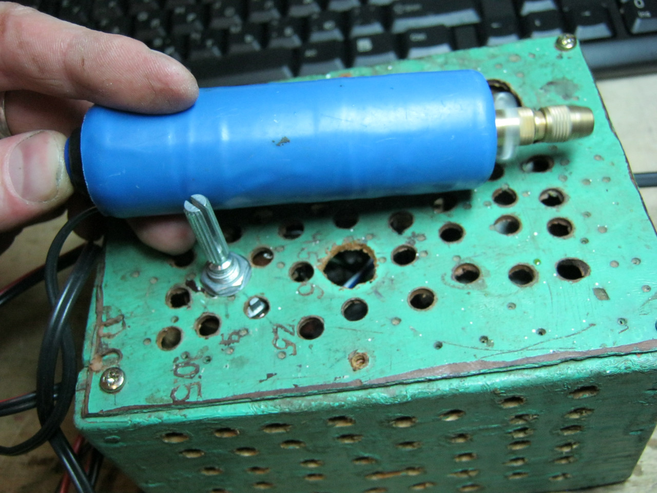
But now we need to do it in a way that is beautiful and practical. To do this, I purchased a case and a digital voltmeter.
We install it into the housing.

Using a drill and a file, holes were made on the front panel. The voltmeter “sits” on two drops of superglue.

After a few hours I got the desired result.
Somehow recently I came across a circuit on the Internet for a very simple power supply with the ability to adjust the voltage. The voltage could be adjusted from 1 Volt to 36 Volt, depending on the output voltage on the secondary winding of the transformer.
Take a close look at the LM317T in the circuit itself! The third leg (3) of the microcircuit is connected to capacitor C1, that is, the third leg is INPUT, and the second leg (2) is connected to capacitor C2 and a 200 Ohm resistor and is an OUTPUT.
Using a transformer, from a mains voltage of 220 Volts we get 25 Volts, no more. Less is possible, no more. Then we straighten the whole thing with a diode bridge and smooth out the ripples using capacitor C1. All this is described in detail in the article on how to obtain constant voltage from alternating voltage. And here is our most important trump card in the power supply - this is a highly stable voltage regulator chip LM317T. At the time of writing, the price of this chip was around 14 rubles. Even cheaper than a loaf of white bread.
Description of the chip
LM317T is a voltage regulator. If the transformer produces up to 27-28 volts on the secondary winding, then we can easily regulate the voltage from 1.2 to 37 volts, but I would not raise the bar to more than 25 volts at the transformer output.
The microcircuit can be executed in the TO-220 package:

or in D2 Pack housing

It can pass a maximum current of 1.5 Amps, which is enough to power your electronic gadgets without voltage drop. That is, we can output a voltage of 36 Volts with a current load of up to 1.5 Amps, and at the same time our microcircuit will still output 36 Volts - this, of course, is ideal. In reality, fractions of volts will drop, which is not very critical. With a large current in the load, it is more advisable to install this microcircuit on a radiator.
In order to assemble the circuit, we also need a variable resistor of 6.8 Kilo-Ohms, or even 10 Kilo-Ohms, as well as a constant resistor of 200 Ohms, preferably from 1 Watt. Well, we put a 100 µF capacitor at the output. Absolutely simple scheme!
Assembly in hardware
Previously, I had a very bad power supply with transistors. I thought, why not remake it? Here is the result ;-)

Here we see the imported GBU606 diode bridge. It is designed for a current of up to 6 Amps, which is more than enough for our power supply, since it will deliver a maximum of 1.5 Amps to the load. I installed the LM on the radiator using KPT-8 paste to improve heat transfer. Well, everything else, I think, is familiar to you.

And here is an antediluvian transformer that gives me a voltage of 12 volts on the secondary winding.

We carefully pack all this into the case and remove the wires.

So what do you think? ;-)

The minimum voltage I got was 1.25 Volts, and the maximum was 15 Volts.


I set any voltage, in this case the most common are 12 Volts and 5 Volts


Everything works great!
This power supply is very convenient for adjusting the speed of a mini drill, which is used for drilling circuit boards.
Analogues on Aliexpress
By the way, on Ali you can immediately find a ready-made set of this block without a transformer.

Too lazy to collect? You can buy a ready-made 5 Amp for less than $2:

You can view it at this link.
If 5 Amps is not enough, then you can look at 8 Amps. It will be enough for even the most seasoned electronics engineer:

Since I resumed my amateur radio activities, the thought of quality and universality has often come to my mind. The power supply available and manufactured 20 years ago had only two output voltages - 9 and 12 volts with a current of about one Ampere. The remaining voltages necessary in practice had to be “twisted” by adding various voltage stabilizers, and to obtain voltages above 12 Volts, a transformer and various converters had to be used.

I got pretty tired of this situation and started looking for a lab diagram on the Internet to repeat. As it turned out, many of them are the same circuit on operational amplifiers, but in different variations. At the same time, on the forums, discussions of these schemes on the topic of their performance and parameters resembled the topic of dissertations. I didn’t want to repeat and spend money on dubious circuits, and during my next trip to Aliexpress I suddenly came across a linear power supply design kit with quite decent parameters: adjustable voltage from 0 to 30 Volts and current up to 3 Amps. The price of $7.5 made the process of independently purchasing components, designing and etching the board simply pointless. As a result, I received this set in the mail:

Regardless of the price of the set, I can call the quality of the board's manufacturing excellent. The kit even included two extra 0.1 uF capacitors. Bonus - they will come in handy)). All you need to do yourself is to “turn on the attention mode”, place the components in their places and solder them. The Chinese comrades took care to mix up what only a person who first learned about a battery and a light bulb could do - the board was silk-screened with the component values. The final result is a board like this:

Laboratory power supply specifications
- input voltage: 24 VAC;
- output voltage: 0 to 30 V (adjustable);
- output current: 2 mA - 3 A (adjustable);
- Output voltage ripple: less than 0.01%
- board size 84 x 85 mm;
- short circuit protection;
- protection for exceeding the set current value.
- When the set current is exceeded, the LED signals.
To obtain a complete unit, you should add only three components - a transformer with a voltage on the secondary winding of 24 volts at 220 volts at the input (an important point, which is discussed in detail below) and a current of 3.5-4 A, a radiator for the output transistor and a 24-volt cooler for cooling the radiator at high load current. By the way, I found a diagram of this power supply on the Internet:

The main components of the circuit include:
- diode bridge and filter capacitor;
- control unit on transistors VT1 and VT2;
- the protection node on transistor VT3 turns off the output until the power supply to the operational amplifiers is normal
- fan power supply stabilizer on 7824 chip;
- A unit for forming the negative pole of the power supply of operational amplifiers is built on elements R16, R19, C6, C7, VD3, VD4, VD5. The presence of this node determines the power supply of the entire circuit with alternating current from the transformer;
- output capacitor C9 and protective diode VD9.
Separately, you need to dwell on some components used in the circuit:
- rectifier diodes 1N5408, selected end-to-end - maximum rectified current 3 Amperes. And although the diodes in the bridge work alternately, it would still not be superfluous to replace them with more powerful ones, for example, 5 A Schottky diodes;
- The fan power stabilizer on the 7824 chip was, in my opinion, not very well chosen - many radio amateurs will probably have 12-volt fans from computers on hand, but 24-volt coolers are much less common. I didn’t buy one, deciding to replace the 7824 with a 7812, but during testing the BP abandoned this idea. The fact is that with an input alternating voltage of 24 V, after the diode bridge and filter capacitor we get 24 * 1.41 = 33.84 Volts. The 7824 chip will do an excellent job of dissipating the extra 9.84 Volts, but the 7812 has a hard time dissipating 21.84 Volts into heat.
In addition, the input voltage for microcircuits 7805-7818 is regulated by the manufacturer at 35 Volts, for 7824 at 40 Volts. Thus, in the case of simply replacing 7824 with 7812, the latter will work on the edge. Here is a link to the datasheet.
Taking into account the above, I connected the available 12 Volt cooler through the 7812 stabilizer, powering it from the output of the standard 7824 stabilizer. Thus, the cooler’s power supply circuit turned out to be, although two-stage, reliable.
Operational amplifiers TL081, according to the datasheet, require bipolar power +/- 18 Volts - a total of 36 Volts and this is the maximum value. Recommended +/- 15.
And this is where the fun begins regarding the 24 Volt variable input voltage! If we take a transformer that, at 220 V at the input, produces 24 V at the output, then again after the bridge and filter capacitor we get 24 * 1.41 = 33.84 V.
Thus, only 2.16 Volts remain until the critical value is reached. If the voltage in the network increases to 230 Volts (and this happens in our network), we will remove 39.4 Volts of DC voltage from the filter capacitor, which will lead to the death of the operational amplifiers.
There are two ways out: either replace the operational amplifiers with others, with a higher permissible supply voltage, or reduce the number of turns in the secondary winding of the transformer. I took the second path, selecting the number of turns in the secondary winding at the level of 22-23 Volts at 220 V at the input. At the output, the power supply received 27.7 Volts, which suited me quite well.
As a heatsink for the D1047 transistor, I found a processor heatsink in the bins. I also attached a 7812 voltage stabilizer to it. Additionally, I installed a fan speed control board. A donor PC power supply shared it with me. The thermistor was secured between the fins of the radiator.

When the load current is up to 2.5 A, the fan rotates at medium speed; when the current increases to 3 A for a long time, the fan turns on at full power and reduces the temperature of the radiator.


Digital indicator for the block
To visualize the voltage and current readings in the load, I used a DSN-VC288 voltammeter, which has the following characteristics:
- measuring range: 0-100V 0-10A;
- operating current: 20mA;
- measurement accuracy: 1%;
- display: 0.28 "(Two colors: blue (voltage), red (current);
- minimum voltage measurement step: 0.1 V;
- minimum current measurement step: 0.01 A;
- operating temperature: from -15 to 70 °C;
- size: 47 x 28 x 16 mm;
- operating voltage required for operation of the ampere-voltmeter electronics: 4.5 - 30 V.


Considering the operating voltage range, there are two connection methods:
- If the measured voltage source operates in the range from 4.5 to 30 Volts, then the connection diagram looks like this:

- If the measured voltage source operates in the range of 0-4.5 V or above 30 Volts, then up to 4.5 Volts the ampere-voltmeter will not start, and at a voltage of more than 30 Volts it will simply fail, to avoid which you should use the following circuit:

In the case of this power supply, there is plenty to choose from for powering the ampere-voltmeter. The power supply has two stabilizers - 7824 and 7812. Before 7824, the wire length was shorter, so I powered the device from it, soldering the wire to the output of the microcircuit.
About the wires included in the kit
- The wires of the three-pin connector are thin and made of 26AWG wire - thicker is not needed here. Colored insulation is intuitive - red is the power supply for the module electronics, black is ground, yellow is the measuring wire;
- The wires of the two-contact connector are current-measuring wires and are made of thick 18AWG wire.
When connecting and comparing the readings with the multimeter readings, the discrepancies were 0.2 Volts. The manufacturer has provided trimmers on the board to calibrate voltage and current readings, which is a big plus. In some instances, non-zero ammeter readings are observed without load. It turned out that the problem can be solved by resetting the ammeter readings, as shown below:

The picture is from the Internet, so please forgive any grammatical errors in the captions. In general, we're done with the circuitry -
Good day, forum users and site guests. Radio circuits! Wanting to put together a decent, but not too expensive and cool power supply, so that it has everything and it doesn’t cost anything. In the end, I chose the best, in my opinion, circuit with current and voltage regulation, which consists of only five transistors, not counting a couple of dozen resistors and capacitors. Nevertheless, it works reliably and is highly repeatable. This scheme has already been reviewed on the site, but with the help of colleagues we managed to improve it somewhat.
I assembled this circuit in its original form and encountered one unpleasant problem. When adjusting the current, I can’t set it to 0.1 A - at least 1.5 A at R6 0.22 Ohm. When I increased the resistance of R6 to 1.2 Ohms, the current during a short circuit turned out to be at least 0.5 A. But now R6 began to heat up quickly and strongly. Then I used a small modification and got a much wider current regulation. Approximately 16 mA to maximum. You can also make it from 120 mA if you transfer the end of the resistor R8 to the T4 base. The bottom line is that before the resistor voltage drops, a drop in the B-E junction is added and this additional voltage allows you to open T5 earlier, and as a result, limit the current earlier.


Based on this proposal, I conducted successful tests and eventually received a simple laboratory power supply. I am posting a photo of my laboratory power supply with three outputs, where:
- 1-output 0-22v
- 2-output 0-22v
- 3-output +/- 16V
Also, in addition to the output voltage regulation board, the device was supplemented with a power filter board with a fuse block. What happened in the end - see below.
Publications on the topic
-
 All codes for cars, money, weapons
Why do we need cheat codes for games and how to use them Game developers, after the next virtual universe is created,...
-
 How to open XPS? XPS file. How to open it? xps reader
The most common cause of problems with XPS file opening is simply the lack of appropriate applications installed on your...